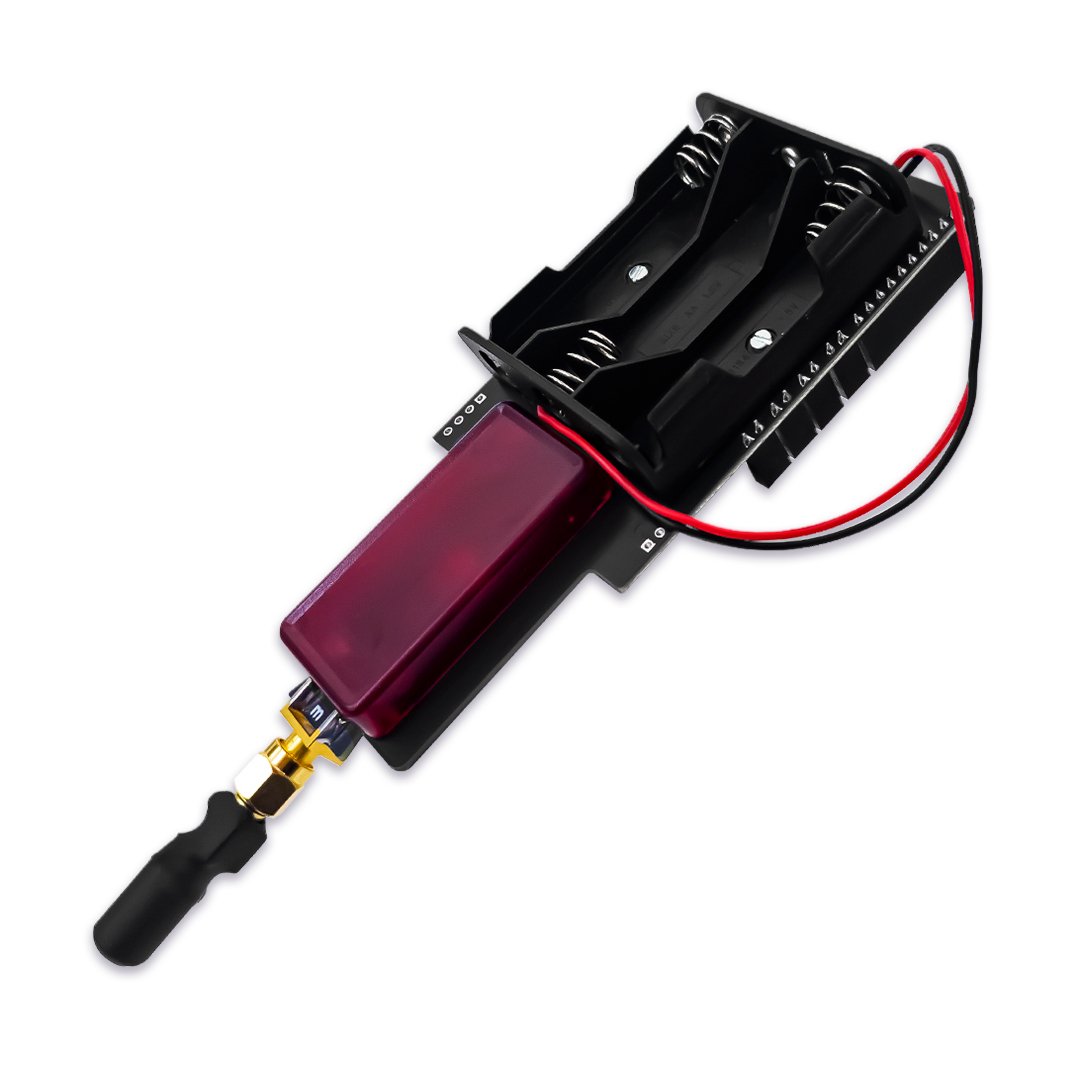

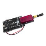
Faulty Cat V2.2
Electromagnetic pulses and voltage glitching in one open-source board, with an SWD pinout scanner and 8-channel logic analyzer — for hardware you're authorized to test.
$120.00
In stock
- Any chip with SWD or JTAG pins — the scanner finds them
- PulseView and sigrok to decode the logic capture
- Pre-flashed firmware — no flashing for a basic EMFI test
- faultycmd CLI/TUI — Windows, macOS, Debian and Arch
In the box
USB cable
Not included
You also need
- 190 GitHub Stars
- Designed and built in Aguascalientes, Mexico
- Hardware CC BY-SA 3.0 · firmware BSD-3-Clause
What is Faulty Cat?
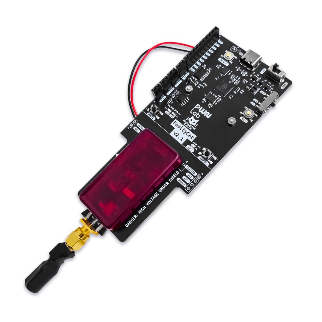
Faulty Cat is a low-cost, open-source electromagnetic fault injection (EMFI) tool for hardware security research, designed specifically for self-study and hobbyist research. Fault injection means deliberately disturbing a running chip to see whether it skips an instruction, crashes or takes a wrong branch — and Faulty Cat does it in two independent ways. EMFI charges a flyback capacitor to around 240–250 V and discharges it into a coil on the SMA output, with pulse widths in microseconds. Crowbar uses a power MOSFET to briefly short the target’s supply to ground, with pulse widths in nanoseconds: roughly 1000x faster, and with no high-voltage capacitor involved. Either technique runs as a single shot in Direct mode, or as an automated delay, width and power sweep in Campaign mode. Use it only on hardware you own or have explicit permission to test.
Prove the target faults before you commit to it
Find the debug pins, then watch the bus
Run a hands-on glitching workshop
Start in 10 minutes
- Turn Faulty Cat on with the ON/OFF switch (SW2). It runs on USB-C or on 3x AA batteries — USB-C takes priority when both are present.
- For a basic EMFI test, no firmware flashing is needed: press ARMING to charge the high-voltage capacitor, then press PULSE once the CHG and HV LEDs light up.
- For parameter sweeps, SWD scanning and the logic analyzer, install the faultycmd host CLI/TUI — a packaged installer for your OS, or
pip install -e .from source. - Run
faultycmd setup-env(Linux and macOS; with sudo on Linux) to install the udev rule and add your user to thedialoutgroup, then check the link withfaultycmd devicesandfaultycmd verify— see the installation guide. - Run
faultycmd updateto flash the firmware build that matches your host tool version, then confirm the exact version match in the CDC2 diag banner or with theversionshell command before you rely on the pairing.
| Weight | .80 g |
|---|---|
| Dimensions | 18 × 12.5 × 3 cm |
| MCU | RP2040 — dual-core ARM Cortex-M0+ at 133 MHz, bare chip on the PCB (not a Raspberry Pi Pico module) |
| Memory | 264 kB on-chip SRAM |
| Flash | W25Q16JV external QSPI flash, 16 Mbit (2 MB) |
| Power | USB-C or 3x AA alkaline batteries (USB-C takes priority); minimum working voltage ~3.8 V; 3.3 V I/O; no battery charger on board, High-voltage section: 0.47 µF capacitor charged to ~240–250 V through two step-up transformers (rated up to 630 V storage) |
| Fault injection | EMFI — ~240–250 V flyback capacitor discharged into a coil on the SMA output, pulse width in microseconds, Crowbar — power MOSFET briefly shorts the target VCC to GND, pulse width in nanoseconds, no HV capacitor involved |
| Pulse width range | Crowbar: 8 – 50,000 ns, EMFI: 1 – 50 µs |
| Execution modes | Direct — single shot, Campaign — automated sweep over the cartesian product of delay, width and power, with a 256-entry on-device result ring buffer |
| Debug and analysis | SWD/JTAG pinout scanner (JTAGulator-style brute force; `scan swd` exposed at firmware v3.0, JTAG verbs WIP for v3.1), 8-channel protocol-agnostic logic analyzer (GP0-GP7, SUMP/OLS, decoded in PulseView/sigrok), BusPirate v1 BBIO, OpenOCD-style JTAG and flashrom serprog v1 compatibility |
| Connectors | USB-C, 8-channel scanner header (GP0-GP7, Conn_01x10 with VCC and GND), External trigger input, 2 pins, level-shifted via TRIGGER_VREF, Analog target-monitor input (GP29/ADC3), SMA for the EMFI coil output, J6 connector for the 3x AA battery holder |
| USB interface | VID 1209 / PID FA17, 4 CDC interfaces: EMFI control, Crowbar control, scanner/shell and target-UART passthrough |
| Board dimensions | 51.32 x 134.62 mm (board only, packaging not included) |
| License | Hardware: CC BY-SA 3.0 (adapted from Colin O'Flynn's ChipSHOUTER PicoEMP design), Firmware: BSD 3-Clause |
Where can I download the FaultyCat firmware? Is the firmware source public, or only binary blobs in Releases?
What's actually different between Faulty Cat and PicoEMP?
Is the schematic available as a PDF, not just as KiCad source files?
What am I allowed to use Faulty Cat for?
You may also like…